more information
Wednesday, August 8, 2018
Friday, April 27, 2018
Autocad basic
Review the basic AutoCAD and AutoCAD LT controls.
After you launch AutoCAD or AutoCAD LT, click the Start Drawing button to begin a new drawing.

You'll notice a standard tabbed ribbon across the top of the drawing area. You can access nearly all the commands presented in this guide from the Home tab. In addition, the Quick Access toolbar shown below includes familiar commands such as New, Open, Save, Print, Undo, and so on.
 |
| Add caption |
Note: If the Home tab is not the current tab, go ahead and click it.
The Command Window
At the heart of the program is the Command window, which is normally docked at the bottom of the application window. The Command window displays prompts, options, and messages.

You can enter commands directly in the Command window instead of using the ribbon, toolbars, and menus. Many long-time users prefer this method.
Notice that as you start to type a command, it is completed automatically. When several possibilities are available such as in the example below, you can make your choice by clicking it or using the arrow keys and then pressing Enter or the Spacebar.
 |
| Add caption |
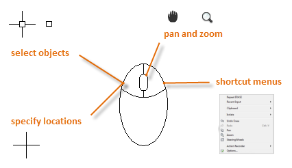
The Mouse
Most people use a mouse as their pointing device, but other devices have equivalent controls.
 |
| Add caption |
Tip: When you look for an option, try right-clicking. Depending on where you locate your cursor, different menus will display relevant commands and options.
New Drawings
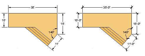
You can easily conform to industry or company standards by specifying settings for text, dimensions, linetypes, and several other features. For example, this backyard deck design displays two different dimension styles.
 |
| Add caption |
All these settings can be saved in a drawing template file. Click New to choose from several drawing template files:
 |
| Add caption |
- For imperial drawings that assume your units are inches, use acad.dwt or acadlt.dwt.
- For metric units that assume your units are millimeters, use acadiso.dwt or acadltiso.dwt.
 |
| Add caption |
The "Tutorial" template files in the list are simple examples for the architectural or mechanical design disciplines with both imperial (i) and metric (m) versions. You might want to experiment with them.
Most companies use drawing template files that conform to company standards. They will often use different drawing template files depending on the project or the client.
Create Your Own Drawing Template File
You can save any drawing (.dwg) file as a drawing template (.dwt) file. You can also open any existing drawing template file, modify it, and then save it again, with a different filename if needed.
 |
| Add caption |
If you work independently, you can develop your drawing template files to suit your working preferences, adding settings for additional features as you become familiar with them.
To modify an existing drawing template file, click Open, specify Drawing Template (*.dwt) in the Select File dialog box, and choose the template file.
 |
| Add caption |
Important: If your company has already established a set of drawing template files, check with your CAD manager before modifying any of them.
Units
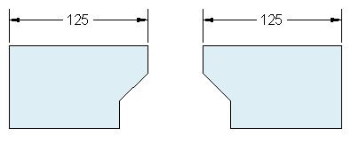
When you first start a drawing, you need to decide what the length of one unit represents—an inch, a foot, a centimeter, a kilometer, or some other unit of length. For example, the objects below could represent two buildings that are each 125 feet long, or they could represent a section from a mechanical part that is measured in millimeters.
 |
| Add caption |
Unit Display Settings
After you decide what unit of length that you want to use, the UNITS command lets you control several unit display settings including the following:
- Format (or Type). For example a decimal length of 6.5 can be set to display as a fractional length of 6-1/2 instead.
- Precision. For example, a decimal length of 6.5 can be set to display as 6.50, 6.500, or 6.5000.
If you plan to work in feet and inches, use the UNITS command to set the unit type to Architectural, and then when you create objects, specify their lengths in inches. If you plan to use metric units, leave the unit type set to Decimal. Changing the unit format and precision does not affect the internal precision of your drawing. It affects only how lengths, angles, and coordinates are displayed in the user interface.
Tip: If you need to change the UNITS settings, make sure that you save the drawing as a drawing template file. Otherwise, you will need to change the UNITS settings for each new drawing.
Model Scale
Always create your models at full size (1:1 scale). The term model refers to the geometry of your design. A drawing includes the model geometry along with the views, notes, dimensions, callouts, tables, and the title block displayed in the layout.
You can specify the scaling that is necessary to print a drawing on a standard-sized sheet later, when you create the layout.
Recommendations
- To open Help with information about the command in progress, simply press F1.
- To repeat the previous command, press Enter or the Spacebar.
- To see various options, select an object and right-click, or right-click a user interface element.
- To cancel a command in progress or if you ever feel stuck, press Esc. For example, if you click in the drawing area before entering a command, you will see something like the following:
 |
| Add caption |
Press Esc to cancel this preselection operation.
Parent topic: The Hitchhiker's Guide to AutoCAD Basics
Next topic: Viewing
Related Reference
- UNITS (Command)
- contect us my website - autocadcoursetech.blogspot.com
Wednesday, April 25, 2018
how to make a autocad degining
How to make a autocad desinnig
1
Decide what project you want to use AutoCAD for. AutoCAD programs cover a broad range of applications. You can find specialized programs for your area of interest, including software focusing on architectural, mechanical, civil, aeronautical or electrical drawing.
 |
| Add caption |
2
Ensure that your computer meets the program's system requirements. AutoCad requires the following:
- 2 GB RAM
- 2 GB of space for installation
- Screen resolution of 1,024 X 768
- Internet Explorer 7.0 or higher
- Application button: The large, red A at the top, left-hand corner of the screen is the application button. Use it to print files and to exit the program.
- Quick-access toolbar: This toolbar sits next to the application button and contains common commands like "Save" and "Open."
- Ribbon: Located below the quick-access toolbar, the ribbon is comprised of a series of tabs (e.g., "Home," "Insert," "Annotate," "View," etc.) that contain groups of standard commands and tools.
- Status bar: The toolbar across the bottom of the screen is the status bar. It mostly consists of control settings that allow you to monitor changes in the drawing.
- Command/prompt toolbar: Directly above the status bar is the command/prompt toolbar. This is where the software communicates with you.
- 5Create a new drawing. From the quick-access toolbar, click "File," and then "New." The new drawing will use 1 of 2 default settings, either imperial or metric. If you want to use specific settings for a drawing, select "Templates" under the Options dialog box. Several Draw a simple figure. Master simple techniques in AutoCAD and practice fundamental skills before moving on to complex drawings. Start with an exercise like drawing a 4-inch horizontal line.
-
6Locate the small gear icon at the bottom of the screen. This is the Workspace icon. Click it and select "2D Drafting & Annotation."
-
7Click the Home icon on the left side of the ribbon.
-
8Select the Line icon from the drop down menu.
-
9Check the text in the command/prompt toolbar. It should show "Command: _ line Specify first point."
-
10Move your mouse inside the drawing area. A + symbol should follow the mouse as you move it.
-
11Click the left mouse button near the center of the drawing area. This is the first point of the line.
-
12Look for the text "Specify next point or [Undo]" in the command/prompt area.
-
13Type "@4<0" in the command/prompt area and hit enter twice.
-
14Your 4-inch line is complete. In this example, @ denotes at the first starting point, 4 represents the unit of measure, < stands for direction, and the number after it, in this case, 0, represents the number of degrees from the horizontal axis.drawing templates come with the program.
-
15Experiment with other drawing options. Learn to draw other shapes and figures like arcs and rectangles, and master other important functions, like erase, change line types and add colors.
-
16Build on what you've learned. As you become proficient with AutoCAD, you'll be able to convert lines into 2D surfaces, surfaces into 3D solids, add realistic material representations, and manipulate light and shadows.
-
17Save your drawing. Go back to the quick-access toolbar, click "Options," "Open" and "Save," and then execute the desired command. To exit the program entirely, click the application button, slide your cursor down to "Exit," and click.
 |
| Add caption |
3
Install the AutoCAD program. The process is a basic installation with step-by-step instructions from the Installation Wizard. It takes about 30 minutes to complete. After installation the AutoCAD icon will appear on your desktop. Double-click the icon whenever you want to start the program.
 |
| Add caption |
4
Familiarize yourself with how to navigate through AutoCAD. The workspace in AutoCAD is divided into 2 distinct areas. The drawing area covers most of the screen and toolbars are anchored above and below the drawing area. They include:
 |
| Add caption |
You're helping people by reading wikiHow

wikiHow's mission is to help people learn, and we really hope this article helped you. Now you are helping others, just by visiting wikiHow.
Water.org is an international nonprofit organization that has positively transformed millions of lives around the world through access to safe water and sanitation. Founded by Gary White and Matt Damon, Water.org pioneers innovative, market-driven solutions to the global water crisis — breaking down barriers to give families hope, health and the opportunity to break the cycle of poverty.
Click below to let us know you read this article, and wikiHow will donate to Water.org on your behalf. Thanks for helping us achieve our mission of helping people learn how to do anything.
What is a autocad?
what is autocad in English
- AutoCAD is a commercial computer-aided design (CAD) and drafting software application. Developed and marketed by Autodesk,[1] AutoCAD was first released in December 1982 as a desktop app running on microcomputers with inter lokeshsuthar120@gmail.com nal graphics controllers.[2] Before AutoCAD was introduced, most commercial CAD programs ran on mainframe computers or minicomputers, with each CAD operator (user) working at a separate graphics terminal.[3] Since 2010, AutoCAD was released as a mobile- and web app as well, marketed as AutoCAD 360.
Subscribe to:
Comments (Atom)


